Installation, Maintenance, and Inspection of
Shut Off Valves
T9450 Series & T9460 Series and Similar Series
In its continuing quest for safety and quality performance, RegO® Products publishes a series of bulletins explaining
the proper installation, inspection, and maintenance of various products. This document is not intended to
conflict with federal, state, or local ordinances or regulations; these regulations should be observed at all
times.
Objective:
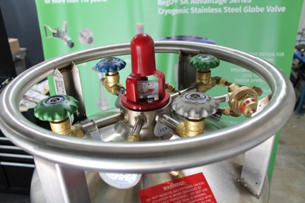
The purpose of this bulletin is to offer guidance for the installation, maintenance, and inspection of RegO cryogenic short stem shut off valves.
Installations
The installation process of the shut off valve depends on the application or kind of products to handle (Cryogenic Liquid or vapor phase).

Cryogenic Liquid Installation
RegO® recommends that the valves in liquid cryogenic service are mounted in a horizontal pipeline with stem RegO recommends that the valves in liquid cryogenic service are mounted in a horizontal pipeline with the stem positioned vertically. Installing in this position will limit the exposure of the stem packing to the cryogenic liquid. If cryogenic liquid is allowed to contact the stem packing seal for prolonged periods of time, then the sealing elements can shrink beyond design limits and may result in a packing leak. An adequate packing seal can be optimized if the stem is within 45° of the vertical position.
For liquid cryogenic installation, it is recommended to use either brazed or back braze threaded end connections to avoid potential leakage through the threads that can occur during thermal cycling. RegO offers a diverse range of different end connections to help fit your specific installation needs.
Cryogenic Liquid Installation Steps:
- Disassemble the valve, fully removing the upper assembly, prior to applying any high temperature heat processes to avoid damage to the soft materials, such as gaskets and seals.
- Ensure that connections are clean and free of any debris.
- Clean the nipple and valve threads and apply flux.
- Position the valve such that the flow arrow is in the proper direction for the intended application.
- The brazing process must be completed according to applicable codes and standards. Proper welding and brazing technique are imperative to ensure the structural integrity of the joint and the components.
NWARNING: USE TORCH PROPERLY; FAILURE TO DO SO MAY RESULT IN LEAKS. A common mistake during the silver brazing process is the improper use of a torch. One common example is when the torch is oversized and produces overheating of the valve body. If the overheating condition is combined with a fast-cooling process, then it can create porosity in the brass body material, which can result in body leaks.
6. Purge and clean the body and pipeline to avoid debris or pollution that could affect the sealing of the valve.
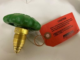
7. After the purging of the valve body and pipeline is complete, it is very important to use a new copper gasket in the valve body. As seen in Figure 3, RegO includes an extra copper gasket attached to the topworks for this purpose. Place the topworks onto the body. Verify that the valve is in the fully open position and thread the topworks finger tight into the body. With a suitable torque wrench and crowfoot wrench apply 900 to 1100 in-lbs (75 to 92 ft-lbs) for the final adjustment.
NOTE 2: If an old gasket is reused the probability of leakage is high due to this gasket having been deformed previously. Some leak channels can appear due to the thermal cycles and improper torque of the top work. Dip the new cooper gasket in water for 5 minutes before installing.
WARNING: DO NOT REUSE GASKETS. If an old gasket is reused, then the probability of leakage is high as the gasket has already been previously deformed and is unable to properly fill the void space in the new position.
WARNING: DO NOT EXCEED THE TORQUE INDICATED; EXCESS TORQUE MAY DAMAGE GASKET AND RESULT IN LEAKAGE AT THIS JOINT. Some leak channels can appear over time, as a result of thermal cycles coupled with improper torque of the topworks. Do not exceed the torque indicated. Excess torque can cause damage to the gasket and cause premature leaking at this joint.
8. Follow all local codes or national codes and standards for pressure testing and leak checking the installaion before start up of the system.
Vapor phase Installation.
- Ensure that connections are clean and free of any debris.
- Clean the nipple and valve threads and apply sealant that is appropriate for the intended service to male thread of the connection.
- Position the valve such that the flow arrow is in the proper direction for the intended application.
- Restrain the valve with a vise or suitable wrench, and using an appropriate wrench for the connection, apply the proper torque to the connection according to applicable codes and standards.
- Follow all local codes or national codes and standards for pressure testing and leak checking the installation before startup of the system.
Inspection
The inspection period and process of the valves depends on the application, service conditions, environment, and regulatory requirements. Many visual inspections can be accomplished without disassembling the valve. The primary inspection points are:
- Packing system
- Bonnet gasket
- Body and bonnet
During this inspection, verify that the valves do not have the below conditions:
1. Any signs of corrosion due to water, salt, industrial pollutants, chemicals, and roadway contaminants.
2. Any physical damage that would prevent proper sealing or that may cause product failure under pressure.
3. Leaks in the valve bonnet area or between the body and end connections of the valve.
Maintenance
The maintenance period and process of the valves depend on the application, service conditions, environment, and The maintenance period and process of the valves depend on the application, service conditions, environment, and regulatory requirements. It is recommended that genuine RegO parts are used. The repair kit part number that applies for the T9450 Series & T9460s and similar Series is T9564-80, depending on the handwheel color the part number is indicated below.
| Repair Kit | Handwheel Color |
| T9464-80 | Silver |
| T9464-80B | Blue |
| T9464-80G | Green |
| T9464-80R | Red |
NOTE: Always replace the gasket whenever the bonnet is removed

Field Topic Conductor :
Carlos Arevalo
Technical Manager/IG & Cryogenics Division at RegO Products
Experienced Technical Manager with a demonstrated history of working in the industrial gases, cryogenic, oil & energy industry. Skilled in Negotiation, Management, Troubleshooting, Business, and Logistics Management. Mechanical Engineer with a Diploma in Modern Management focused in Management from Universidad de Carabobo.