Excess Flow Valve Operation
Field Topics are intended to provide useful information to the network of authorized LP-Gas and Anhydrous Ammonia distributors regarding the proper use of RegO® products. Warning Bulletins covering many of the hazards involved are available from RegO for more detailed information. These bulletins can be found in our L-500, and NH3-102 catalogs. Neither the Field Topic or the Warning Bulletins are intended to conflict with federal, state, or local ordinances and/or regulations, which should be observed at all times. This information also is not intended to be a substitute for or to supplement any training in the safe handling and use of propane and related equipment, as required by any applicable law. By providing this material, ECI assumes no responsibility for providing any such training. Only individuals properly trained in the safe handling and use of propane and related equipment should be permitted to do so, and by providing this information, ECI does not assume responsibility for providing such training.
For more information on LP Gas system requirements, refer to Liquefied Petroleum Gas Code (NFPA 58), National Fuel Gas Code (NFPA 54), National Propane Gas Association Safety Handbook, the RegO LP-Gas Serviceman’s Manual L-545, RegO catalogs L-500/NH3-102, ANSI K61.1 Safety Requirements for Storage and Handling of Anhydrous Ammonia, as well as any applicable local codes and ordinances.

What are excess flow valves and what are their purpose?
Excess flow valves are a protective device to help control the discharge of product in the event of complete breakage of pipelines or hose ruptures preventing a possible catastrophic product discharge.
An excess flow valve is a spring-loaded check valve which will close when the flow of fluid or vapor through the valve generates sufficient force to overcome the power of the spring holding it open.
How do excess flow valves differ from Backchecks?
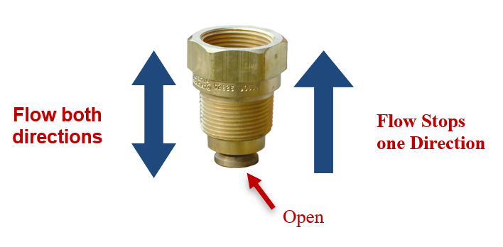
Excess flow valves are simple spring devices that are normally open to allow flow in either direction and can be actuated to stop flow in one direction.
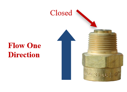
Back check valves are simple spring loaded devices that are normally closed and can be actuated to allow flow in only one direction.
Excess Flow Valves: How They Work
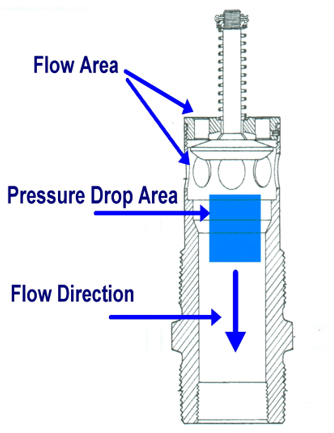
STEP ONE:
When liquid or vapor flows through the excess flow valve in the direction indicated, a pressure drop beneath the poppet is created
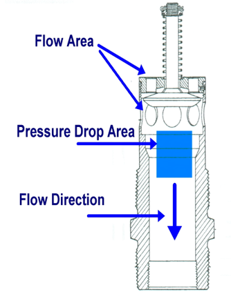
STEP TWO:
When the volume of product exceeds the rated capacity of the valve, the pressure drop becomes great enough to overcome the spring force holding the seat disc away from the seat.
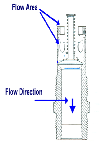
STEP THREE:
The seat disc will quickly move towards the seat, stopping the flow of product.
Excess flow valves: After the valve closes
1.
A. When an excess flow valve has closed due to a line break or surge in the system it does not seal off 100%
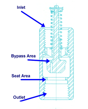
Every excess flow valve has a bypass feature not exceeding a #60 drill which allows a small amount of product to pass downstream of the seat disc
B. The valve will automatically reset itself as the pressure will pass through the bypass area to reach the downstream side; which is then increased to match the pressure on the upstream side
2.
C. At this point the excess flow spring pushes the seat disc assembly away from the seat, and the valve opens up to allow flow

D. If there had been a line break downstream from the excess flow valve, the flow through the bypass area would not be great enough to allow the valve to reopen flow
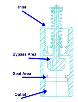
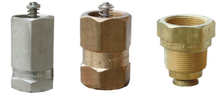
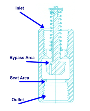
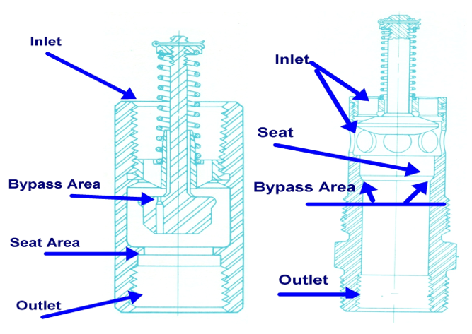
There are several methods to incorporate the bypass feature into an excess flow valve, here are a few examples:
Excess Flow Valves: Closing Flow
Excess flow valves are rated in closing flows in gallons per minute and/or cubic feet per hour.
These valves are marked with the specific closing flow which is tested by UL for conformance to UL 125 Standard for LP-Gas and NH3 Valves.
Excess Flow Valves: Proper Selection
To select the correct closing flow for the application:
- Determine the maximum GPM or CFH flow the system will require
- Add 50% to this value and use it to select the appropriate closing flow
System Flow Sizing Factor Selected Closing Flow
Example: 50 GPM X 150% = 75 GPM Flow

Should you have any questions or concern, please contact Paul Courson
Paul Courson
LPG & NH3 Technical Director
O: +1 336.446.7292
Paul.Courson@regoproducts.com